|
|
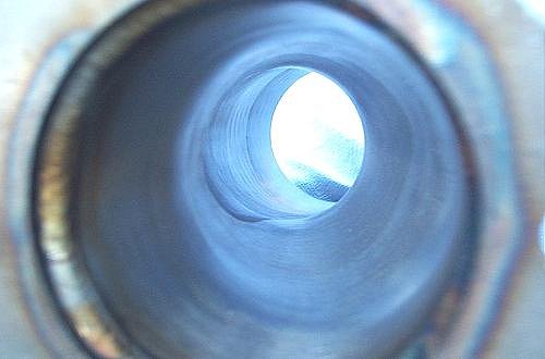
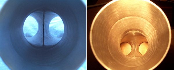
So what's this Y-Pipe I keep talking about? Some readers may be wondering why I'm not using the X-Pipe that everyone always mentions as being so important to S14 performance. Well, an X-Pipe and a Y-Pipe perform identical functions. Unlike an H-Pipe, which serves mainly to equalize the pressure between two different exhaust pipes, an X-Pipe or Y-Pipe acts as a "diffuser". As an exhaust pulse comes down one of the two header pipes it hits the X-Pipe/Y-Pipe and "sees" an expanding section. The expansion acts to slow down the flow and increase the pressure. This in turn creates a negative pressure reflection which travels back up the opposite header pipe. If the header lengths are tuned correctly then this negative pressure pulse arrives at the exhaust valve of the opposite cylinder just in time to help scavenge the last of the exhaust gasses from that cylinder (as well as helping to pull in the arriving fresh charge). This happens during the overlap period of the camshaft. For an X-Pipe it's obvious that the cross-sectional area available to an exhaust pulse doubles as the pulse comes in one of the branches of the X and exits through two others. For a 2.25" X-Pipe the area goes from 3.56 in� to 7.13 in�. For a Y-Pipe the cross-sectional area increases from what it is at the inlet, to what it is at the outlet. So for the Y-Pipe that I designed with Burns, which is 2.25" IN to 3.00" OUT, the cross-sectional area goes from 3.56 in� to 6.51 in�. Not much different than the X-Pipe. The following photo vividly illustrates how the flow coming into a Y-Pipe essentially "sees" a divergent section: |
|
|
This is a view through one of the two inlets of the Y-Pipe looking out through the single exit. Notice that from the point of the view of an exhaust pulse, the Y-Pipe looks like a divergent section. The other branch of the Y-Pipe can be seen joining in about half way along the section. As an exhaust pulse enters the Y-Pipe it hits the diffuser section which causes a pressure pulse. This causes a negative pressure reflection to travel up the opposite branch of the Y. To re-iterate, the idea is that this negative pressure pulse arrives at the exhaust port of the opposite cylinder just in time to help "suck" the remaining exhaust gases from that cylinder during the end of the exhaust stroke. With the aid of camshaft overlap, this suction will actually help draw the incoming fresh charge on the intake side into the cylinder. Pressure pulses and reflections travel at the speed of sound and are unaffected by tube diameter. Thus the primary means of "pressure tuning" an exhaust system is by varying the length between junctions. |
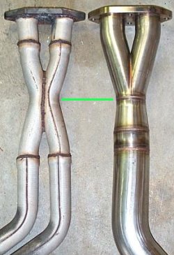 So, if one wants to preserve the factory pressure tuning it is necessary to locate the "pinch point"
on the Y-Pipe in the same location as the pinch point on the factory X-Pipe. This can be seen at left,
although this is a SuperSprint center section, not a factory X-Pipe. Nonetheless, the X is in the same
place, and the green line shows the corresponding "center" of the Y to be in the same place. Note that
there is no reason the the pinch point has to be in the same place. But if you move it you will change
the RPM point at which the X/Y pipe becomes effective.
So, if one wants to preserve the factory pressure tuning it is necessary to locate the "pinch point"
on the Y-Pipe in the same location as the pinch point on the factory X-Pipe. This can be seen at left,
although this is a SuperSprint center section, not a factory X-Pipe. Nonetheless, the X is in the same
place, and the green line shows the corresponding "center" of the Y to be in the same place. Note that
there is no reason the the pinch point has to be in the same place. But if you move it you will change
the RPM point at which the X/Y pipe becomes effective.
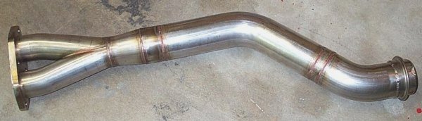
The photo at left also clearly shows the diffuser section of the Y-Pipe. In other words, the tube diameter in the Y does not suddenly jump from 2.25" to 3.00". This would cause a very strong pressure reflection, but it would only be effective over a very narrow RPM band. It would also lead to a nasty recirculation zone, and a lot of flow energy would be lost to viscous dissipation. But that does not relate to pressure tuning. By using the diffuser to gradually bring the tube diameter from 2.25" to 3.00" one can spread out the effectiveness of the Y-Pipe over a wider RPM band. This improvement is not free however, and comes at the expense of a reduction in the strength of the negative pressure reflections. Nonetheless, this is considered a worthwhile compromise. |
|
|
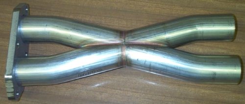
If the builder prefers to stick with a dual exhaust layout, in the interest of improved ground clearance for example, then a Burns X-Pipe could be designed and built. The photo below shows the Burns Y-Pipe from the outlet, looking towards the inlets. The craftsmanship of the Burns product is readily apparent. |
|
|
Page 5 » |
|
|