|
|
|
|
|
|
|
|
|
S14/S38 Valve Adjustment |
|
|
Procedure w/ pictures |
|
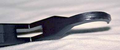
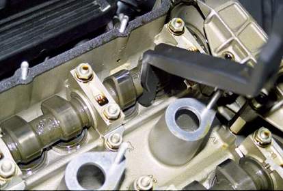
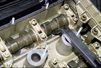
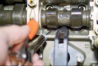
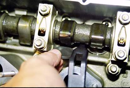
Checking Valve Clearance: 10. Valve clearance specifications should be indicated on a sticker on the driver's side shock tower. This sticker recommends 0.28mm to 0.33 mm (0.0110" to 0.0130") cold for both intake and exhaust. 11. Starting at cylinder number one (closest to the front of the car), rotate the engine with the 36mm socket on the crank until the intake cam lobes (the pointy parts) point up at you (picture 4). 12. Using the feeler gauge, measure valve clearance for each of the two valves between the cam and valve shim (picture 5). Record this measurement. 13. Repeat this procedure until all intake valve measurements have been taken and recorded. 14. Repeat this procedure for all exhaust valves. Removal and Replacement for Out of Spec Shims These steps need only be performed for shims that are out of spec. Follow the same steps for removing either single (i.e., one valve) or both (i.e., both valves) shims on a single cylinder. With careful planning it might be possible to "recycle" out of spec shims from some valves on other out-of-spec valves. However, be sure not to rotate the engine (even by hand) without shims in every valve bucket, or damage to the cam lobe may result. 15. Rotate the engine until the cam lobes on the out-of-spec shims point up at you (picture 4). 16. Rotate the valve buckets for the shims that need to be removed until the slot in the upper edge of the bucket faces the corner of the head casting (picture 4). This is done so these slots will be facing you when you depress the buckets with the tool. 17. The Valve bucket compression tool has two hooks, one on either end. These hooks are used to lever the tool under the camshaft and depress the valve buckets (both valves on one cylinder at the same time). Each hook has a ridge, or spline, cast into the back of it. These splines are different widths and make the hooks intake and exhaust specific. The hooks are not interchangeable. The intake spline is the wider of the two (picture 6). 18. Insert the Valve bucket compression tool between the cam lobes on the desired cylinder, being careful to center the hook's spline between the two buckets (picture 7). Carefully press down on the tool until the valve buckets have been fully depressed (the tool will bottom out on the spark plug shaft, picture 8). 19. Using a small nipple (like the one used to fill a football), blow compressed air through the slot in the valve bucket and under the valve shim (picture 9). This should dislodge the shim from the bucket. 20. Remove the shim with a suitable tool (e.g., magnet, small pliers) and measure with calipers or micrometer . It is best to plan to measure worn shims versus reading the thickness off the back, since very worn shims will vary from the stated thickness and may have their markings worn off. 21. Add existing valve gap to existing shim thickness and subtract desired valve gap to get new shim thickness. For example, if a valve gap measured 0.38mm, and the shim measured 3.6mm, and the desired gap was 0.28mm (any value in the manufacturer's range is okay), the new shim would measure: 0.38 + 3.6 - 0.28 = 3.70mm. Thus, the new shim would need to be 3.70mm thick. 22. Insert new valve shim into bucket (just slide it in, picture 10). Repeat for second valve if necessary. 23. Carefully lift up on the Valve bucket compression tool to release compression on valve buckets. 24. Repeat procedure for all affected valves. Buttoning Up: 25. Reinsert spark plugs in holes they were removed from and tighten to specification. 26. Clean all gasket surfaces thoroughly. 27. Carefully install new spark plug hole gaskets (2) and valve cover gasket. 28. Carefully install valve cover. Install eighteen (18) 10mm acorn nuts with wave washers. 29. Insert spark plug wires into appropriate holes and press firmly to connect. Bolt down the spark plug harness (careful not to dislodge the brass inserts) with the two remaining 10mm acorn nuts and wave washers. Reposition the distributor cover and reinsert the three (3) 8mm bolts and wave washers into the holes. Tighten to specification. 30. Reinsert the valve cover vent hose and tighten clamp. 31. Reinstall fan or lower airbox assembly (ensuring the mass air and altitude sensor plugs are properly connected) 32. Remove tire chocks. 33. Enjoy! |
|
|
|
|
|
|
|
|
|
|