Figure 1 Figure 1 shows the layout of an E30 rear trailing arm. We are looking down the axis of rotation of the trailing arm (i.e. along the pivot points). This axis is rotated 15° (in a horizontal plane) relative to the chassis but for our purpose here that does not matter. In order to calculate the "effective" rear wheel rate we perform a balance
of torque's about the trailing arm axis of rotation. A "moment balance"
in engineering parlance. There is one important aspect of calculating moments
(torque's) that we need to keep in mind. Refer to Figure 2 below:
When measuring the distances L1 and L2 as shown in Figure 1, it is necessary to remember this detail concerning the definition of torque. When I initially tried to determine the effective wheel rate on my E30 M3 I forgot about this. As I was calculating the distance L2 shown in Figure 1, I measured from the rear contact patch to the trailing arm bushing. This is equivalent to using 1.4 ft. to calculate the torque in Figure 2 - which we just learned is incorrect. It has been too many years since I took the class at UCLA I suppose 8^) Now we need to consider which torque's act on the E30 rear trailing arm. Let us examine a moment balance (balance of torque's) about an axis through the trailing arm bushings. Any force acting ON the trailing arm AT the bushings contributes no torque and cancels out. Thus we are left with the torque caused by the tire contact patch (F2 acting through the rear hub) and the torque caused by the rear spring (F1 acting through the spring perch). As long as the trailing arm is not moving these torque's balance each other out. In other words F1(L1)= F2(L2). A sketch of the torque balance around the trailing arm axis is shown below in Figure 3:
So how does all this relate to spring rates? Spring rates are
usually expressed as lbs/in. In other words, if we compress a given
spring by one inch, how much resistance does it offer? If a spring
that is compressed 1" pushes back with a force of 500 lbs than that spring
is rated as 500 lbs/in (assuming it is linear).
What we want to do here is determine a similar rate for the rear wheel.
How much force does it take to push the rear wheel up a distance of one
inch? The force required will be equal to the "effective rear wheel
rate". A torque balance on the trailing arm will help us answer
this question.
If we push up on the trailing arm and displace it by 1 inch
(dw = 1" in Figure 1) - how far does this compress the spring
(ds in Figure 1)? From similar triangles we calculate ds as:
We will call the spring rate of the rear spring k1 (lbs/in). The force exerted on the trailing arm by the compressed spring is:
Now use the moment balance on the trailing arm to calculate F2:
Divide through by dw to yield the "effective rear wheel rate":
The nice thing about this equation is that it applies to any type of suspension, not just the E30 trailing arms. All you need to know is the length of the two lever arms L1 and L2. Thus we can also use this equation to calculate the "effective front wheel rate". The front wheel rate is closer to the spring rate than on the rear, but it is still not exactly equal to the spring rate. For the BMW E30 chassis we get the following table. If you know your spring rates then you can calculate your wheel rates using the yellow formulas. 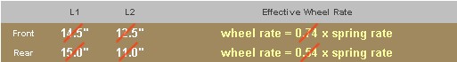
Ed. Note: The numbers in the table are now known to be incorrect.
|