|
| |||
 The sketch on the left shows a piston moving down a cylinder bore as a consequence of
combustion pressure.
This pressure is converted to a force on the piston.
(It is interesting to note that for a given combustion pressure, a bigger bore will give
rise to a larger force on the piston)
The sketch on the left shows a piston moving down a cylinder bore as a consequence of
combustion pressure.
This pressure is converted to a force on the piston.
(It is interesting to note that for a given combustion pressure, a bigger bore will give
rise to a larger force on the piston)
The piston in turns pushes on the rod, and this force is subsequently used to create a torque on the crank, causing it to rotate. Thus the burning of fuel and air is converted to mechanical energy that can be used to propel an automobile down the road (or track). The length of the rod is depicted as L1 in the figure. Similarly the length of the crank arm is denoted by L2. Observe that L2 is not equal to the stroke. The stroke is in fact twice L2. The ratio of the rod length to stroke is called "rod ratio" and is a useful term to quantify the kinematics (relative motion) of the piston as the crank completes a cycle. Rod ratio can also be used to quantify the dynamics of piston motion (the relative forces) but that is for another article. | |||
|
The equation for the rod ratio is as follows:
The total distance that the piston moves down the bore is solely determined by the stroke of the crank. But both the speed, and the acceleration of the piston are dictated by the rod ratio. The piston speed and acceleration can have numerous effects on the performance of an engine. The velocity of the piston (it's speed) can be important in determining how the intake charge is pulled through the ports and past the valves. A fast moving piston will pull harder on the ports, creating a larger Delta-P to "suck" air into the cylinder on the intake stroke. Here one might think of correlating the point of maximum piston speed to the point of maximum valve lift for example. The acceleration of the piston on the other hand, leads to forces on the rod and main bearings, as well as on the wrist pin. These forces put a limit on the rpm's that the bottom end of the engine can reliably withstand. The rod ratio also determines the "dwell-time" of the piston at top-dead-center (TDC) during combustion. This means that the position of the piston relative to the point at which maximum combustion pressure occurs can be altered through changes in rod ratio. This could be used to try to correlate the point of maximum combustion pressure to the point at which the piston has the greatest mechanical advantage on the crank for instance. In fact, the very nature of the combustion process can be affected by the position of the piston, and how long it dwells at TDC. These are all interesting topics, but in this article we restrict ourselves to an investigation of piston displacement and velocity, and we concentrate mostly on piston acceleration. | |||
|
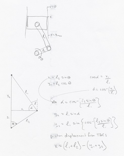
The equation that governs piston position along the bore is readily determined. A "back of the envelope" derivation is shown in the following link: | |||
| Click here for a derivation of the piston kinematics equation... | |||
|
Once the piston displacement from TDC is known, it is a relatively simple matter to determine the piston velocity and the acceleration. This was done via an Excel spreadsheet which generates curves of piston position, velocity and acceleration as a function of the crank angular rotation. A case with all three curves shown together is presented in the following link. Note that the piston acceleration was divided by 1000 to keep it on the same scale as the other two curves. The situation modeled here is an Evo III spec S14 engine with 87 mm stroke and a 144.25 mm long rod: | |||
| Click here for piston displacement, velocity and acceleration curves... | |||
|
Observe that the velocity and acceleration curves are not perfect sinusoids. They approach being perfect sinusoids as the rod is lengthened (increasing the rod ratio). Also, the maximum piston velocity occurs well before 90° ATDC. Furthermore, the maximum piston acceleration occurs at TDC, being roughly twice as large here as compared to BDC. But the peak piston acceleration at TDC occurs very briefly, while near BDC the piston is accelerated upwards at a relatively constant rate for almost 70 degrees of crank rotation. This curve was constructed for 8000 rpm. Clearly at a lower rpm the velocity and accelerations would be smaller, while the displacement would remain the same. | |||
|
So, on to the question of interest: Can we use a longer rod to decrease piston acceleration, and thereby build a bottom end capable of reliably sustaining higher rpms? | |||
| Next page » | |||
|
| |||
|
|