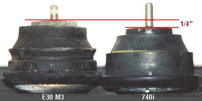
 This side-by-side photo compares the stock E30 M3 motor mount to the 740iL motor mount.
Note that the 740iL mount is 1/4" shorter. Thus using these mounts will lower your
engine approximately 1/4". If you still run the mechanical fan then you will have to move
or modify the shroud to prevent interference. Lowering the front of the engine will also
change your driveline alignment. I chose to fix this by shimming down the tranny. But this
does not seem absolutely necessary, based on the experiences of other E30 M3 owners
who have installed lower engine mounts.
This side-by-side photo compares the stock E30 M3 motor mount to the 740iL motor mount.
Note that the 740iL mount is 1/4" shorter. Thus using these mounts will lower your
engine approximately 1/4". If you still run the mechanical fan then you will have to move
or modify the shroud to prevent interference. Lowering the front of the engine will also
change your driveline alignment. I chose to fix this by shimming down the tranny. But this
does not seem absolutely necessary, based on the experiences of other E30 M3 owners
who have installed lower engine mounts.
The advantage of lowering your engine should not be dismissed. The engine weighs maybe 200-250 lbs fully integrated. Getting it a 1/4" lower with little effort will have a positive effect on handling. The difference won't be earth shattering - but the little things add up when trying to create a fast car. Note the upper stud on the 740iL mount - it is too long and must be trimmed to match the length of the stock mount, at least on the passenger side. Otherwise it will interfere with the exhaust header. I just went ahead and trimmed all the studs, top and bottom, to match the length of the studs on the stock mount. |
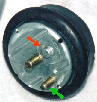 Speaking of studs, the 740iL motor mounts come with a second "locating stud" on the bottom side.
This second (smaller) stud must be cut off and ground flush in order that the mounts can
be fit to the E30 M3 subframe. This smaller stud is illustrated by the green arrow in the
photo at left.
Speaking of studs, the 740iL motor mounts come with a second "locating stud" on the bottom side.
This second (smaller) stud must be cut off and ground flush in order that the mounts can
be fit to the E30 M3 subframe. This smaller stud is illustrated by the green arrow in the
photo at left.
Note the locating stub, highlighted by the red arrow at left. Depending on how one chooses to install the 740iL motor mounts, it may be necessary to grind off this stub on one of the two mounts. The reason for this is as follows: On the stock E30 M3 motor mounts, the upper and lower mounting studs are concentric (they lie on a common axis). However, on the 740iL mounts (as well as on the E28 mounts) the upper and lower mounting studs are NOT concentric. This will be shown below. |
Ed Note: Jake Larsen, a sharp thinking E30 M3 owner has found a better way to implement these mounts. Jake discovered that if one grinds off the locating nubs, but leaves the secondary (smaller) studs intact, then the 740i motor mounts can each be rotated 90° and letting the secondary studs go into the slots on the subframe where the locating nubs would normally go. Not only does this leave your engine centered in the car, it also shifts the engine backwards by 1/4". This is the best of both worlds, the engine is lower and farther back, and the subframe need not be modified. The splined sleeve in the driveshaft easily accommodates this change. Great idea Jake - wish I had thought of it 8^) If you chose to go this route it will supersede some of what you read below... |
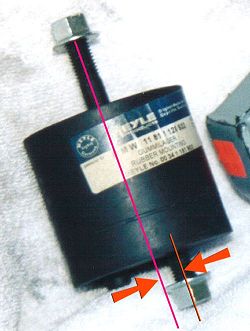 The photo at right shows a motor mount from the E28 5-series. This is one of several types
of alternative motor mounts that can be used on the E30 M3. It also displays a common trait of these
alternative mounts - the mounting studs are not concentric. Thus if one were to install these mounts
by guiding the locating stubs into the appropriate slots in the subframe, then the upper studs,
which attach to the "arms" coming down off the block, will be too close together.
The photo at right shows a motor mount from the E28 5-series. This is one of several types
of alternative motor mounts that can be used on the E30 M3. It also displays a common trait of these
alternative mounts - the mounting studs are not concentric. Thus if one were to install these mounts
by guiding the locating stubs into the appropriate slots in the subframe, then the upper studs,
which attach to the "arms" coming down off the block, will be too close together.
One popular solution to this dilemma is to grind off the locating stub on one of the motor mounts and then to flip this mount 180° about a vertical axis. The net results is that both upper mounting studs will be offset in the same direction - either to the left or to the right, depending on which mount you flip. This might sound fine, but the net result is that the front of your engine is offset about 1/4" to one side. Regardless of the implications on driveline alignment, this did not seem like a desirable solution to me. It should be noted though, that many E30 M3 owners have followed this path without any adverse effects in the short term. |
 The sketch on the left displays the effects of flipping one motor mount with non-concentric studs.
The engine will be shifted to one side by a distance roughly equal to the diameter of a motor mount
stud (i.e. about 1/4"). Because the motor mount platforms on the subframe are angled, the engine
will also end up cocked sideways a bit, but this is a secondary effect.
The sketch on the left displays the effects of flipping one motor mount with non-concentric studs.
The engine will be shifted to one side by a distance roughly equal to the diameter of a motor mount
stud (i.e. about 1/4"). Because the motor mount platforms on the subframe are angled, the engine
will also end up cocked sideways a bit, but this is a secondary effect.
My solution to this issue was to slot the holes in the subframe where the motor mounts are installed. This allows the 740iL mounts to be slid outwards, which in turn brings the upper mounting studs back into proper alignment with the "arms" coming down off the block. It is essential that the subframe be suitably reinforced in the area of the motor mounts when undertaking this approach. The holes in the aluminum "arms" which extend down to the motor mounts from the block can also be enlarged a bit to gain extra clearance. Between slotting the holes in the subframe and slotting the holes in the aluminum arms, it is not too tough to implement non-concentric motor mounts without shifting the engine sideways. Note that the E28 5-series mounts suffer the same trait as the 740iL mounts. Both have the mounting studs in a non-concentric configuration. |
|
Page 3 » |