|
|
|
|
|
| Rod Ratio - Dynamics | |||||
| |||||
|
|

|
|
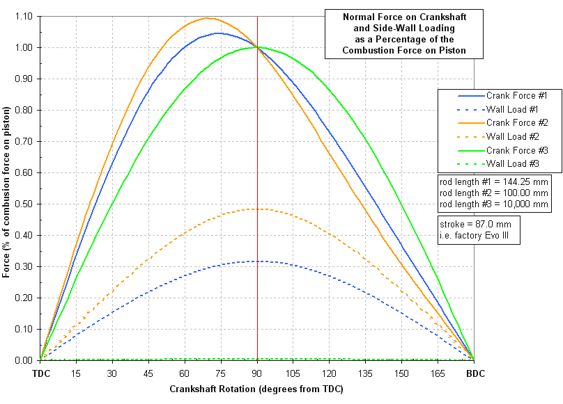
Here we see a plot of the normal force on the crank (i.e. the torque producing portion of the rod force) as well as the side-wall load on the cylinder bore as a function of the crank angle (as the piston moves from TDC to BDC through the power stroke). Both forces are shown for three different rod lengths. A stock S14 rod length (144.25mm), a very short 100mm rod, and a very long rod (10,000mm = 10m which is effectively an infinitely long rod). The stroke is held constant at 87mm (i.e. an Evo III S14 crank) thus varying the rod length also changes the rod ratio. Keep in mind that these forces are shown as a percentage of the force on the piston. But the force on the piston due to combustion is not constant through the power stroke. Thus in reality the side-wall load and crank normal force are further modified by the changing combustion force. This graph details only the "geometric" effects of rod ratio on wall load and crank load. Another way of thinking of it is that these graphs assume that the combustion pressure is constant through the power stroke, sort of like MEP (mean effective pressure). Regarding the side-wall load, we see that it is largest when the crank is half way through the power stroke (crank at 90° past TDC). We also see that as the rod becomes infinitely long that the wall loading goes to zero, as we would expect. This is true regardless of how the combustion force changes. A longer rod (stroke being equal) will always reduce side-wall loading, which is one reason why long rods are desirable. Longer rods also reduce peak piston acceleration at TDC and cause the piston to "dwell" longer at TDC which can work with combustion pressure to produce more work on the crank. Now consider the normal force on the crank. For an infinitely long rod this force peaks at 90° past TDC on the power stroke. Also, for an infinitely long rod the maximum normal force on the crank is equal to the force on the piston (which we have assumed to be constant here). As the rod is made shorter the maximum normal force on the crank occurs sooner in the stroke, and it also becomes larger than the average force on the piston due to mechanical advantage. Sounds great right? But remember that the price is increased side-wall loading. Furthermore, the peak normal force on the crank is not the only important parameter in determining engine torque. We also want to maximize the area under the force vs. rotation curve. Even though the exact variation of the combustion force through the power stroke may not be known, a few facts can be stated. Most performance camshafts will have the exhaust valve opening well before BDC. The combustion gases are "exhausted" while there is still some pressure in the cylinder so that this pressure can help start the gases flowing along the exhaust tract. This is referred to as "blow-down". Thus, on a typical performance engine, the last 70° or so of the power stroke does not directly contribute to torque production (which may surprise those not aware of it). For this reason alone it makes sense to bias the peak normal force on the crank more towards TDC, and this happens with a shorter rod. Also, with ignition occurring well before TDC, the maximum combustion pressure is going to occur
not long after TDC (never before hopefully The only way to obtain the ideal rod length (or rod ratio) from theory is if the combustion pressure
is exactly known as a function of piston position. This is not easy information to obtain,
and the problem is further
compounded by the fact that the combustion pressure depends on the piston position. So an
iterative solution would be required. For a high level F1 team, for example, such an
analysis would certainly be an option. But for most
engine builders it boils down to testing (trial and error). Luckily for many engine types this testing
has already been performed by others (often by the factory race teams, as is the case for the BMW S14).
| |||
|
Click here to download the force spreadsheet... | |||
|
| |||
|
|
|
|
|
|