 I have always wanted to replace
my E30 M3's non-adjustable "L-shaped" factory control arms with something stiffer, adjustable, and with less friction
in the joints. The BMW Motorsport E30 M3 Group-A racecars had such control arms of course, so the path is laid out.
All one needs to do is follow it. I admit to also taking some ideas from the Porsche Motorsport 930/935 racecar suspension
design.
I have always wanted to replace
my E30 M3's non-adjustable "L-shaped" factory control arms with something stiffer, adjustable, and with less friction
in the joints. The BMW Motorsport E30 M3 Group-A racecars had such control arms of course, so the path is laid out.
All one needs to do is follow it. I admit to also taking some ideas from the Porsche Motorsport 930/935 racecar suspension
design.
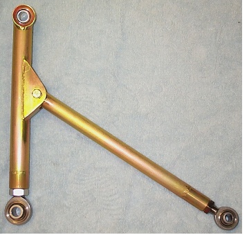
One of the control arms I built is shown at left. The most obvious thing to note is the proper triangulation. The factory "L-shaped" control arms on the E30 and E36 cars do offer a lot of room for the wheels to turn at full lock, but they also allow the front wheels to wander about under heavy cornering and braking. This is a highly undesirable situation in a performance car. The popular aluminum control arms are worse in this regard, as they use approximately the same volume of metal as the steel control arms, except that aluminum is less stiff than steel. In terms of friction, the factory ball joints are not bad. Similarly, the factory rubber lollipop bushing is fairly low friction (as are all rubber bushings designed to twist). But the common replacement bushings for the lollipop; Delrin, Polyurethane, vertical spherical bearing etc. are all high friction joints, relatively speaking. One should not underestimate the advantage of ultra-low friction in suspension points. The effect is quite noticeable. The car is not only more stable and predictable, but more comfortable as well. All the bearings for these Gr-A style control arms are NHBB (New Hampshire Ball Bearing). These are aerospace parts, with a price to match (the large inner rod ends cost over $100 each). But the quality in terms of low friction and durability are worth the price. Since I live in the U.S. I chose to spec all bearings and fasteners as SAE standard. Metric would have been nice, but aerospace spec metric bearings and fasteners are still difficult to obtain in the States, and I wanted replacement parts to be easily obtainable. |
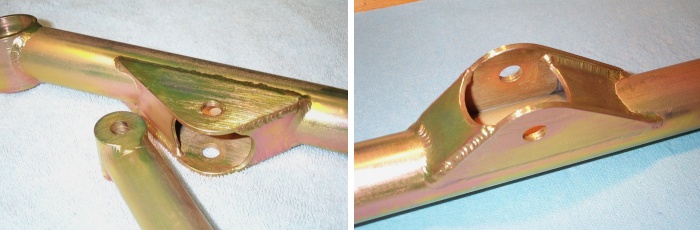
 At right we see one of the control arms disassembled into its component pieces. The main arm that connects the
hub carrier to the subframe controls lateral wheel motion, and is commonly called a "track rod"
(it can also be interpreted as controlling track width). The second arm,
which extends from the track rod back to where the factory lollipop is located, controls fore/aft wheel motion
and can be called a "radius rod". Terminology for suspension links is not always well standardized, but
these are the names I will use here.
At right we see one of the control arms disassembled into its component pieces. The main arm that connects the
hub carrier to the subframe controls lateral wheel motion, and is commonly called a "track rod"
(it can also be interpreted as controlling track width). The second arm,
which extends from the track rod back to where the factory lollipop is located, controls fore/aft wheel motion
and can be called a "radius rod". Terminology for suspension links is not always well standardized, but
these are the names I will use here.
Note that the radius rod attaches to the track rod at what appears to be its mid-section (it is actually a bit farther out when the inner rod end is taken into account). This would appear to leave a substantial portion of the track rod "cantilevered" out past the triangulation point. This is indeed true, and is necessary to provide room for the front wheels to turn, as we shall see later on. On the next iteration I will box up the track rod in the horizontal plane to give it greater stiffness out past the attachment point of the radius rod. The track rod is thick wall 4130, so flex is not large in any case, but one can never be too rigid when it comes to suspension links. Below are shown two detail photos of the attachment point of the radius rod to the track rod. All material is 4130 alloy steel. All welds are TIG (Tungsten inert gas). |
|
|
What about heat treating? Those readers familiar with metallurgy will know that the heat from welding removes the hardness (strength) in the region near the welds. The proper way to build an alloy steel part is to heat treat it after welding to bring the steel back to its original specification. However, the heat treating process invariably distorts and warps the parts in question. Sometimes a fixture can be used during the heat treat process to prevent warping, though this is not always possible. Otherwise the parts need to be physically straightened after heat treating, which can be a time consuming process. It is therefore not uncommon to see designers/fabricators at all but the highest levels of motorsport simply increase the thickness of the tubing to make up for the degradation in strength after welding. The final part will not have the ultimate strength-to-weight ratio that it could have had, were it thinner and heat treated. But often it is more than enough, and that is what I chose to do here. The Gr-A style control arms that I built for example, as strong and stiff as they are with fairly thick walled tubing, still display less unsprung mass than the factory aluminum control arms. |
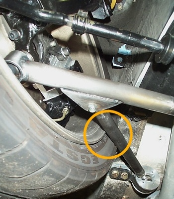 It was previously mentioned that the attachment point of the radius rod to the track rod cannot be too far
outward, as it will cause interference with the wheel/tire at full lock. The picture here illustrates
this issue. The orange circle highlights the area of contact. And it is easy to see that moving the
radius rod further out for better triangulation will reduce the amount that the front wheels can be
turned.
It was previously mentioned that the attachment point of the radius rod to the track rod cannot be too far
outward, as it will cause interference with the wheel/tire at full lock. The picture here illustrates
this issue. The orange circle highlights the area of contact. And it is easy to see that moving the
radius rod further out for better triangulation will reduce the amount that the front wheels can be
turned.
This one of those classic engineering compromises. For a track-only car one might decide that full lock capability is not as important, and move the radius rod out. This is in fact what was done on the BMW Motorsport Gr-A E30 M3 racecars. And this allowed better triangulation of the track rod, so that it could in turn be made from smaller/thinner material to reduce weight. My car is still street driven, and I wanted a better turning radius, so I had to compromise. I moved the radius rod in and beefed up the track rod to compensate. On the next iteration I might make due with a larger turning radius in order to improve triangulation of the control arm, but I worry about some of the tighter corners encountered on auto-x courses. You certainly do not want to have to make a 3-point turn there! |