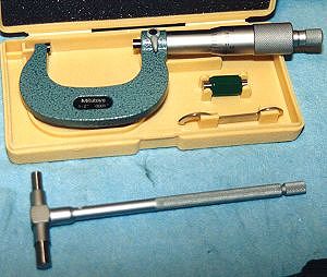
 Here are the two basic tools one needs in order to accurately measure rod bearing clearance.
To measure the outside diameter of the crankshaft rod bearing journal one uses an outside micrometer. And to measure
the inside diameter of the rod bearings one uses a telescoping snap gauge or a dial bore indicator, the picture
shows a snap gauge in this case.
Here are the two basic tools one needs in order to accurately measure rod bearing clearance.
To measure the outside diameter of the crankshaft rod bearing journal one uses an outside micrometer. And to measure
the inside diameter of the rod bearings one uses a telescoping snap gauge or a dial bore indicator, the picture
shows a snap gauge in this case.
The dial bore indicator is the preferred instrument for measuring the inside diameter of a bore/cylinder. Unfortunately they are very expensive (around $350 for a good one). The snap gauge can be purchased for about $35. The only drawback is that the snap gauges have a rather limited range of measurement so you have to buy two separate ones. One snap gauge for the rod bearings and one for the main bearings. MSC Industrial Supply Co. and McMaster Carr both offer a wide variety of accurate measuring tools. |
| Measuring the OD of the rod bearing journals on the crank is fairly straightforward. The most important thing is that the user know how to use and read a micrometer. I opted not to pay extra for a digital micrometer. Thus, I had to take a little while to get used to the procedure for reading the measurements off of the handle of the micrometer. It's quite easy once you figure it out. The hard part is getting repeatable measurements as operator technique can play a part in the value achieved. How tightly you screw the micrometer onto the part being measured is particularly critical. |
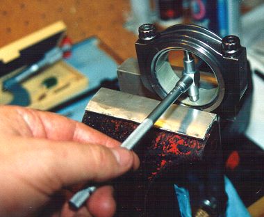 To measure the ID of the rod bearings one first installs them in a rod. The rod bolts must then be torqued/stretched
to their proper value. This "crushes" the rod bearings inside the big end of the rod so that good contact is achieved
between the backsides of the bearings and the rod. This helps conduct heat away from the bearings. With the bearings
in their crushed position the ID of the bearings is established and can be measured using the telescoping snap gauge
as shown in the picture. Note that the bearing ID should be measured along the axis of the rod as the ID across
the parting lines will be slightly larger. The hole formed by the crushed rod bearings is intentionally "out-of-round"
- the idea being that the hole becomes round when the rods are loaded during operation.
To measure the ID of the rod bearings one first installs them in a rod. The rod bolts must then be torqued/stretched
to their proper value. This "crushes" the rod bearings inside the big end of the rod so that good contact is achieved
between the backsides of the bearings and the rod. This helps conduct heat away from the bearings. With the bearings
in their crushed position the ID of the bearings is established and can be measured using the telescoping snap gauge
as shown in the picture. Note that the bearing ID should be measured along the axis of the rod as the ID across
the parting lines will be slightly larger. The hole formed by the crushed rod bearings is intentionally "out-of-round"
- the idea being that the hole becomes round when the rods are loaded during operation.
Once the telescoping snap gauge is locked on the ID of the bearings, it is carefully slid out and the actual dimension is determined with the outside micrometer. The snap gauge does not have any markings on it. It is simply a tool to transfer the ID to the outside micrometer. Thus two steps are required in order to take one measurement and this invariably is a source of error, which is one of the reasons that a dial bore gauge is preferred if you have one. Another reason that a dial bore gauge is preferred is that the handle is much longer than on the snap gauge. This makes it much easier to keep the gauge perpendicular to the surfaces being measured. Any small deviation here will also affect the achieved values. Bearing clearances should be measured down to 0.0001" (one ten thousandths of an inch) so it pays to take your time. With a little patience I was able to get repeatable measurements and had some confidence in my results. |
|
Results for rod bearing clearance » |
|
|