|
|
|
|
|
| "Drive-by-Wire" Throttle Pedal |
|
|
|
 The BMW E46 M3 comes equipped with an electronic "drive-by-wire" throttle pedal.
There is no mechanical connection between the throttle pedal and the butterfly plates
inside the throttle bodies. Instead, when one depresses the throttle pedal, it merely sends
an electrical signal to the engine management computer. This signal is interpreted by the computer
as a desired level of acceleration from the driver. The computer then sends out the correct
signal to an electric stepper motor in order to correctly position the throttle plates.
The BMW E46 M3 comes equipped with an electronic "drive-by-wire" throttle pedal.
There is no mechanical connection between the throttle pedal and the butterfly plates
inside the throttle bodies. Instead, when one depresses the throttle pedal, it merely sends
an electrical signal to the engine management computer. This signal is interpreted by the computer
as a desired level of acceleration from the driver. The computer then sends out the correct
signal to an electric stepper motor in order to correctly position the throttle plates.
Thus, for instance, if the driver completely floors the throttle at, say 1000 rpm, the actual throttle butterflies might not completely open. They might open just enough to provide maximum acceleration without bogging the engine. The computer would then automatically open them further as rpm's climb and the engine can handle the additional air. It is difficult to know exactly how the throttle butterflies respond to inputs from the throttle pedal, as we do not know how the software algorithm is constructed, and the mapping may be rpm dependent. However, when driving an E46 325i (as an example), it is quite apparent that the amount of throttle given by the computer is not always directly correlated to the input at the pedal. This effect is not as obvious on the E46 M3, but it seems probable that this sort of software behavior was also part of the E46 M3 control system for either emissions management, driveablity, or perhaps some other reason. The point here being that there is not necessarily a direct relationship between the position of the throttle pedal and the positions of the throttle butterfly plates on a modern drive-by-wire automobile, which includes all modern BMW's. In many cases the relative positions of the pedal and the plates will be the same, but in other cases they might be different, depending on what the DME determines is optimum for the situation at that moment. |
 It is easy to see how a "drive-by-wire" throttle system
greatly simplifies the implementation of traction control and driving stability control.
In fact, the introduction of these technologies on road cars was hardly possible
before the advent of electronic throttle control.
It is easy to see how a "drive-by-wire" throttle system
greatly simplifies the implementation of traction control and driving stability control.
In fact, the introduction of these technologies on road cars was hardly possible
before the advent of electronic throttle control.
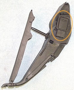
The actual sensor that converts the mechanical position of the throttle pedal into an electronic signal can be seen on the right-hand side of the pedal assembly. It looks quite similar to a TPS (throttle position sensor) which would usually be seen on the throttle body of an earlier engine management system (such as an E30 M3 or E36 M3). And it is essentially identical in that it converts an angular position into a voltage. But here the sensor is a Hall effect device, as opposed to a potentiometer (variable resistor) as was used on previous versions of the M3 for TPS functions. This Hall effect sensor can be seen on the side of the throttle pedal assembly in the photo (inside the orange oval). Ed. Note: Additional research has determined that at least some of the very early E46 M3's did still use a traditional potentiometer to detect throttle pedal position. The Hall sensors were gradually phased in during production, probably between 2001 and 2002. A Hall effect rotary position sensor would generally have three pins. A 5V input, a ground, and an output (ranging from 0V - 5V depending on position). The E46 M3 throttle pedal sensor has six pins. This is in part due to the fact that the sensor is internally redundant. It is in fact two sensors in one. There is a high range output (ranging from roughly 2V-4V) and a low range output (ranging from roughly 0.4V - 0.8V). Thus if the DME receives either no signal, or an out-of-range signal, from its primary source then it automatically defaults to the redundant source so that the car can still function. |
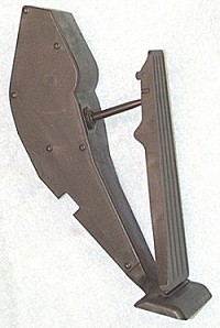
 In the first photo on this page one can see the six screws that hold the cover plate
on to the throttle pedal assembly. I was quite curious to find out what was inside. How is the
mechanical position of the throttle pedal converted to a rotary position of the Hall effect
sensor? What is the return spring mechanism and mostly, how is that annoying kick-down detent
implemented? (this is an SMG throttle pedal)
In the first photo on this page one can see the six screws that hold the cover plate
on to the throttle pedal assembly. I was quite curious to find out what was inside. How is the
mechanical position of the throttle pedal converted to a rotary position of the Hall effect
sensor? What is the return spring mechanism and mostly, how is that annoying kick-down detent
implemented? (this is an SMG throttle pedal)
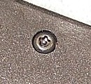
Unfortunately the six screws that attach the cover plate are of a rather unusual design as seen in the photo. I certainly have nothing in my tool box that would fit this. So I used a reverse drill bit to back out the screws. If done carefully this merely destroys the screws (which can be replaced with something more conventional) and does not damage the housing. Well, let's see what's inside... |
| Next page » |
|
|
|
|
|